A Motorola 68000 (m68k) retro computing project
Last week I finished my first actually working retro computing project: a 1980’s Motorola 68000 educational board remake by Jeff Tranter. The original design is called a TS2, Jeff did a great job modernizing it, swapping hard to find chips with more easily obtainable ones and creating an open PCB design for it in KiCad.
I can connect to it using PuTTY:
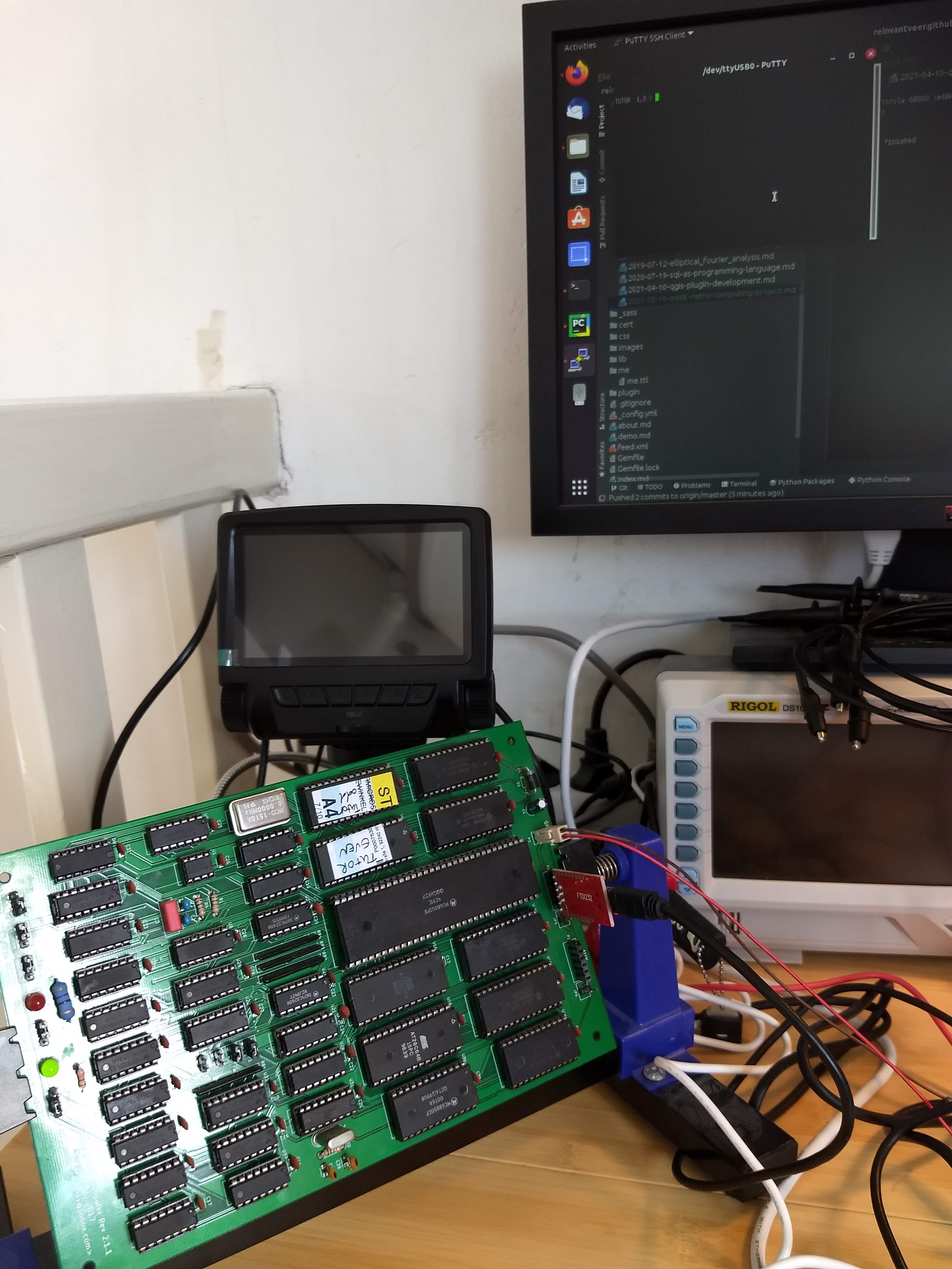
It’s hard to actually see, but in the top right of the picture the terminal says:
TUTOR 1.3 >
I’m pretty proud that I have it up and running that far, it isn’t my first attempt at building retro computer hardware and it can be both awesome and pretty difficult at times. Debugging hardware with my scope is a skill that comes with its own learning curve.
I had a couple of earlier attempts. One was on a hybrid 68008/CPLD board by Steve “Big Mess O’Wires” Chamberlin. The design is pretty cool because it uses an easier to use Motorola 68008 which is code-compatible with the 68000 but has a smaller address and data bus, so less things to mess up. Also, it has enough RAM and ROM to run an early version 2 of the Linux kernel! But it proved too difficult for my humble soldering skills to get the CPLD SMD flat package soldered on the board. So now I just stick to through-hole soldering :)
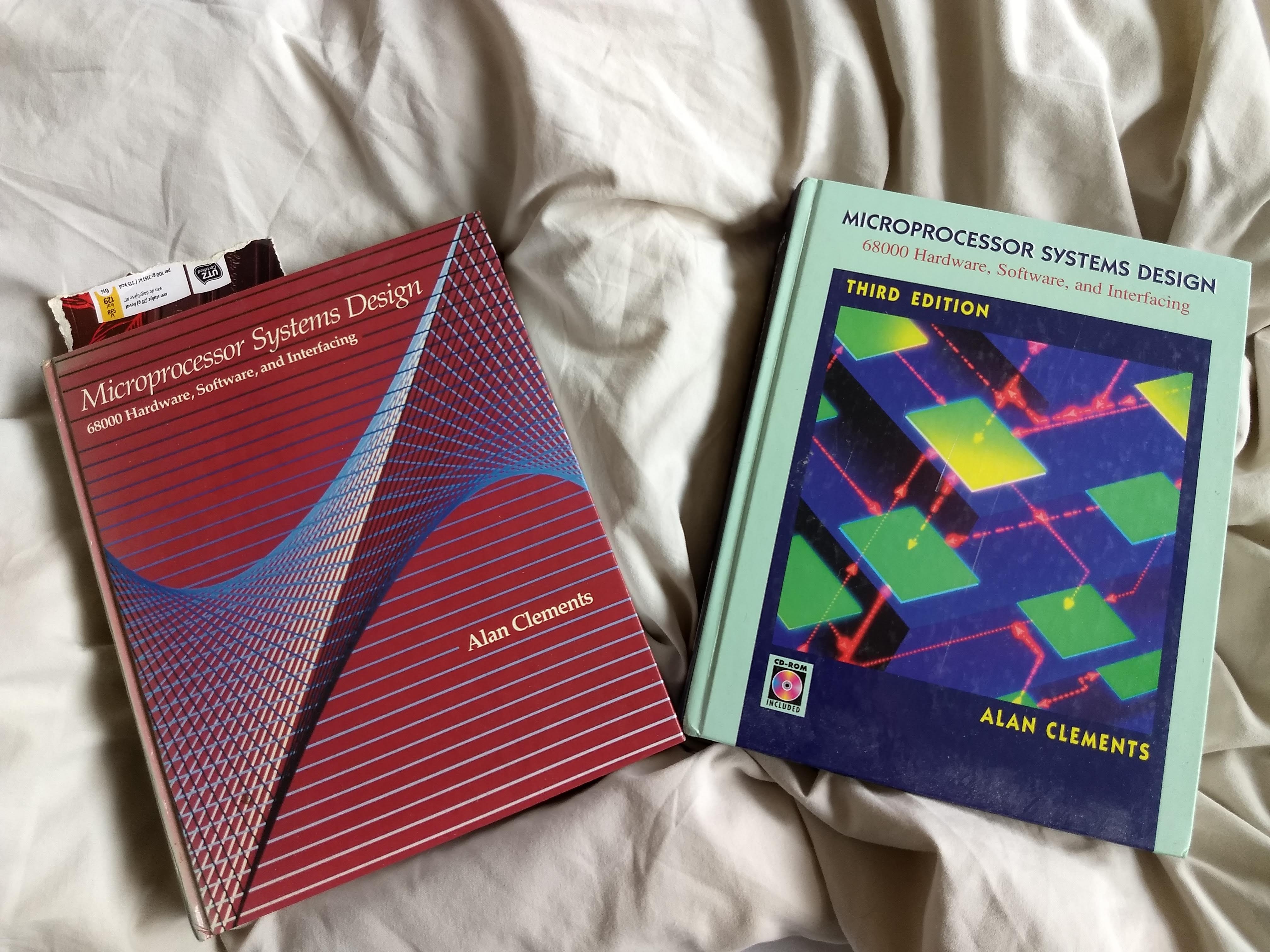
This brought me to Jeff Tranter’s 68000 project. He created the PCB and component placement based on Alan Clements’
“Computer Systems Design”, on of the few books of which I own two editions (one for the included CD-ROM).
The TS2 educational board design is described in detail by Jeff Tranter here, but it’s peculiar in several aspects:
- It uses no programmable chips anywhere except for the ROMs of course. That means that all the address decoding logic, power-on reset circuitry and data acknowledgement circuitry is implemented in TTL logic. The chip count is, expectedly, on the large size with 36 (!) chips on a pretty sizeable board. The upside is, of course, the cost: the TS2 board was supposedly a lot cheaper to build than Motorola’s own Educational Computer Board that went for a rather pricey $495
- Despite the chip count, only 32kb of ROM and 32kb of RAM are available. This makes sense from an educational point of view: there’s no requirement for large software packages to run on this kind of hardware.
- It has a “single-stepping” (or more aptly a single-bus-cycle-stepping) circuit that can be operated using physical switches.
- There’s data acknowledgement speed selection options using jumpers 1 thru 4 to allow for slower, cheaper RAM or ROM chips. Jeff swapped ultraviolet-erasable 2764 ROM chips to electrically-erasable 28C64s, which are of course much easier to use, for example with ubiquitous and low-cost TL866II-type programmers.
- The current board design has no keyboard input, no computer screen output and no board connectors other than two serial ports and the power connector. This means it’s pretty much impossible to attach board peripherals at the moment.
All in all, it is a very cool build, I contributed back some minor updates to the board and the software and I hope to do some more cool stuff with it, write some programs and flash it to the board. I don’t know whether it will fit in ROM, but porting a version 2 of minix to the TS2 would be awesome.
Jeff’s design featured on Hackaday.io in February 2017.